2 installed metallizers · capacitor-grade PP/PET processing
Manufacturing platform
Specialist technology. In-house control.
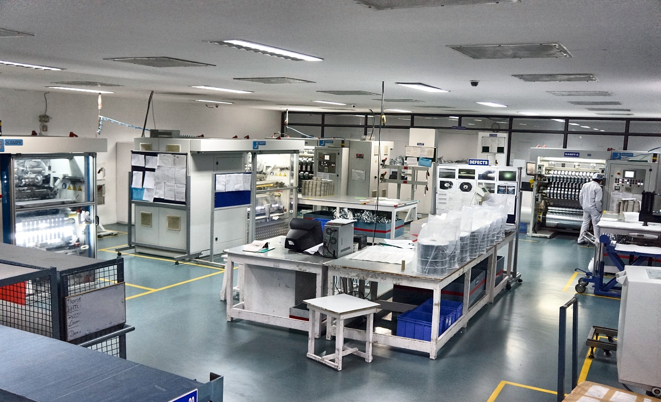
Multiple dedicated metallization and slitting lines support standard, repeat and custom production.
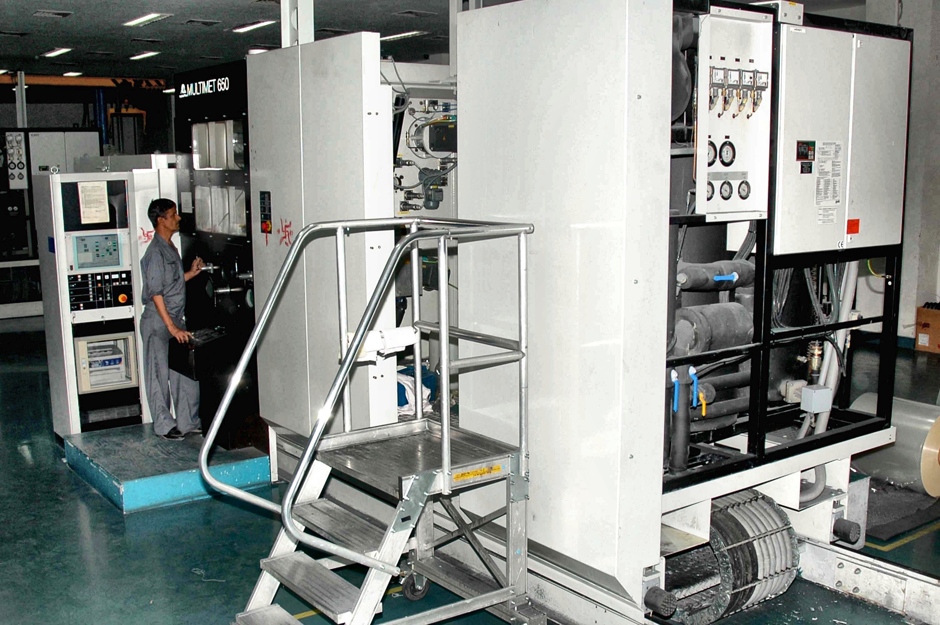
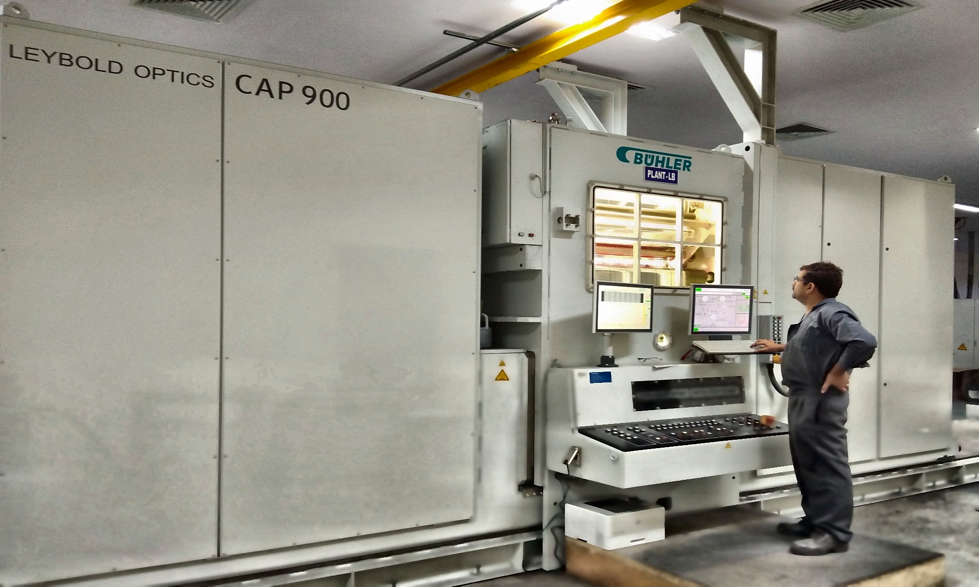
2 installed Bühler / Leybold Optics metallizers
1 latest Bühler Leybold Optics capacitor-film metallizer
6 KAMPF Germany · 5 Vacotec Korea
Technology depth
Where precision engineering becomes film performance.
The value is not the machine badge alone. It is repeatable layer resistance, stable margins, gentle handling of ultrathin film and a clean, consistent finished roll.
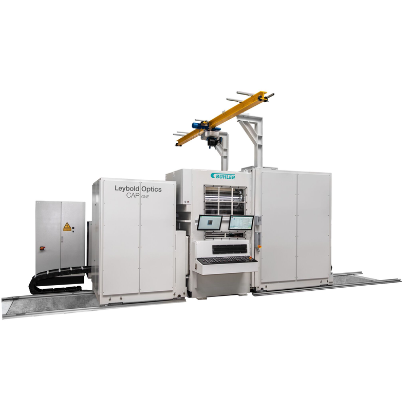
Official supplier technology imageBÜHLERLeybold Optics · capacitor metallization
Control the layer while it is being created.
- 500–900 mm standard coating-width range on the current CAP platform
- Controlled aluminium layer thickness and resistance
- DISS real-time monitoring of layer profiles and free-margin widths
- SuperBias thermal management and efficient substrate cooling
- Closed-loop free-margin oil evaporation on equipped configurations
- Plain, profiled, segmented and stacked aluminium / Al-Zn layers
 Official supplier technology image
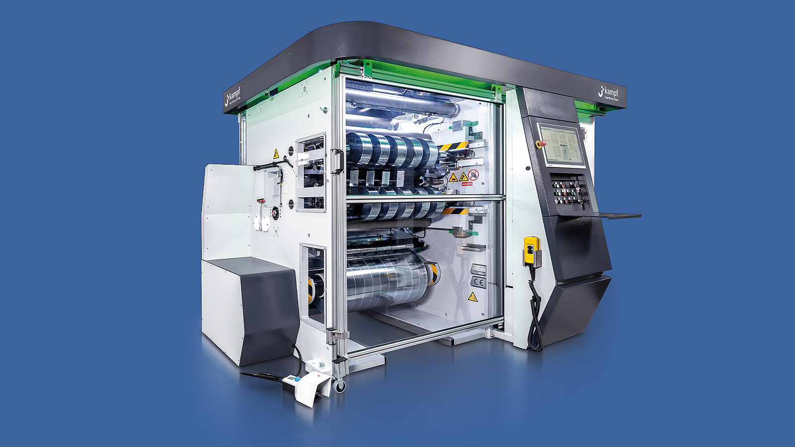
KAMPFMicroSlitter · capacitor-film slitting
Cut precisely without disturbing the film.
- Sensitive centre / surface direct-drive winding
- Integrated unwinder with pre-compensation and tension-measuring rollers
- Razor straight and high-shape-accuracy wave cutting
- Pre-clearing, pinhole counter, camera control and edge-trim options
- >4.5 mm straight and >9 mm wave on the current supplier platform
- Current-platform maxima: 700 m/min straight · 350 m/min wave
Current Bühler CAP and KAMPF MicroSlitter figures are shown as a supplier-platform benchmark. Dhruv's installed-line ratings are stated separately below and the final production route is confirmed against each customer drawing.
Film Properties
Precision Slitting and Wave Cut Engineering
Precision slitting
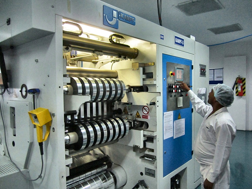
The finished roll is a precision product.
- 11 machines
- Total slitting platform
- 6 + 5
- KAMPF Germany · Vacotec Korea
- Class 10,000
- Particle verification every six months
- 4.5 mm
- Microslit capability
- 500 m/min
- Mechanical speed
- Wave cut
- From 8.5 mm stated
Wave-cut engineering
Geometry selected for the capacitor design.
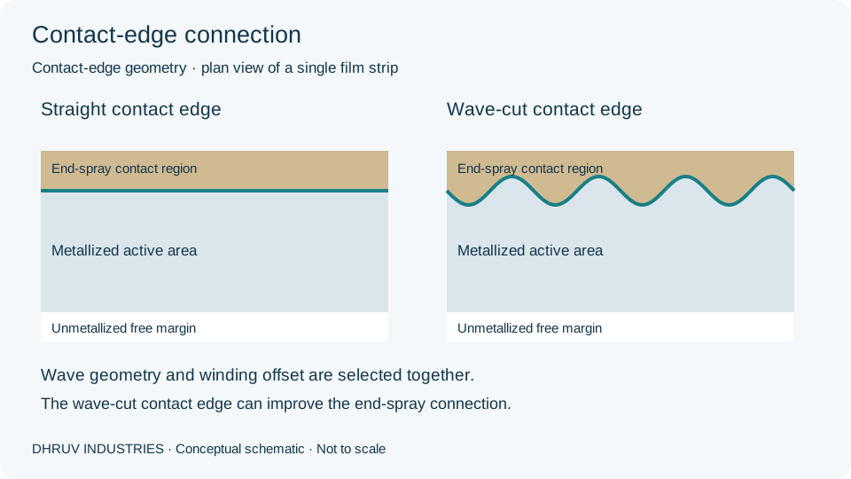
Wave cutting can be applied at the contact edge or the free-margin edge. Wavelength and amplitude are controlled against the approved drawing.
Alongside standard wave profiles, Dhruv can customise the wavelength to suit the customer's capacitor design and manufacturing requirements. Edge position, wavelength and amplitude are agreed against the customer-approved specification before production.
∿∿∿∿∿∿
W15-1500.15 mm double amplitude
1.5 mm wavelength
∿∿∿∿∿
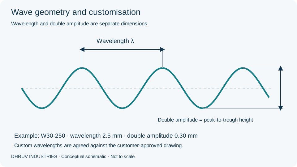
W30-2500.30 mm double amplitude
2.5 mm wavelength
∿∿∿∿
W80-5000.80 mm double amplitude
5.0 mm wavelength
∿∿∿
Extended high wave1.00 mm double amplitude
10 mm wavelength
Precision slitting in detail
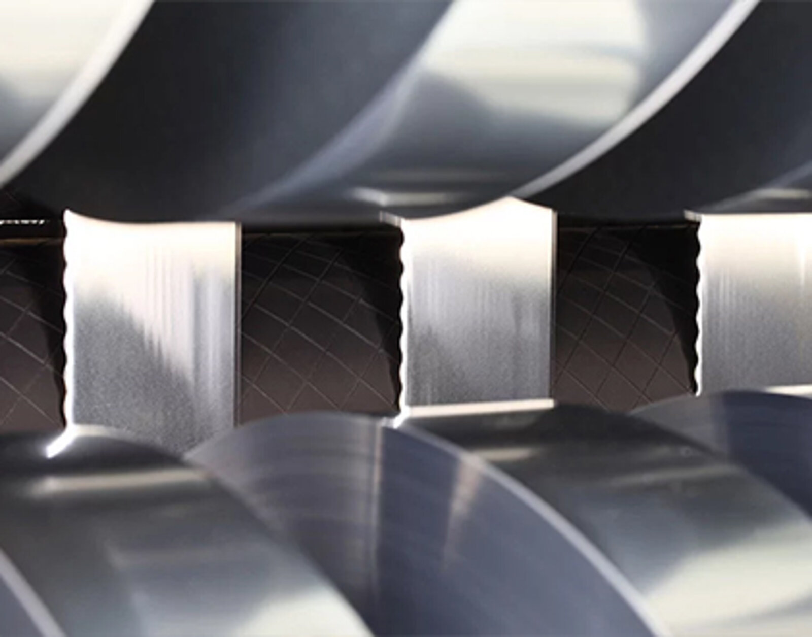
Technical reference photographs from the KAMPF MicroSlitter platform.
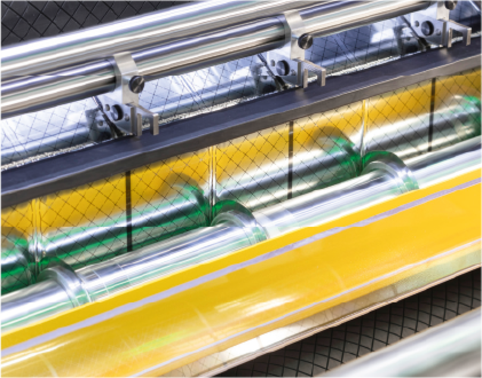
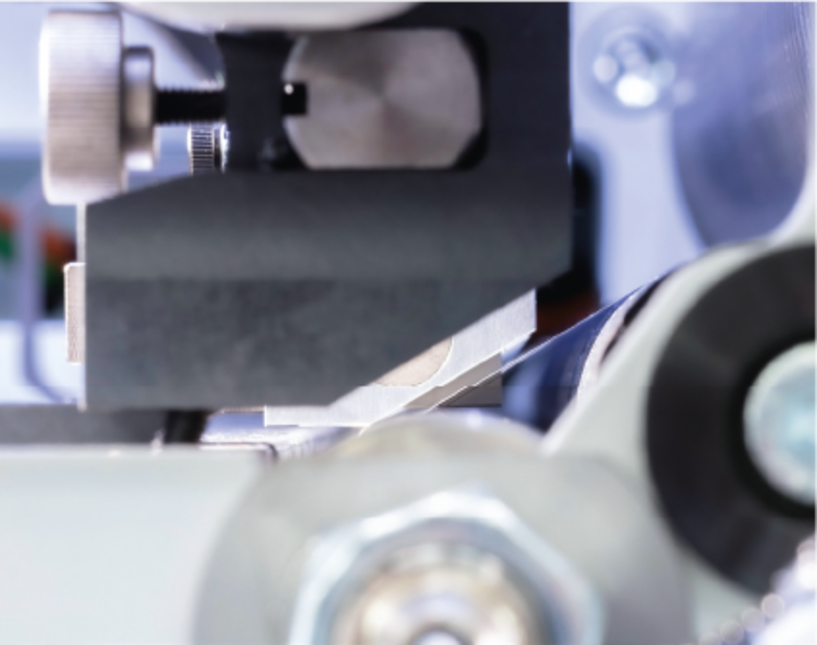
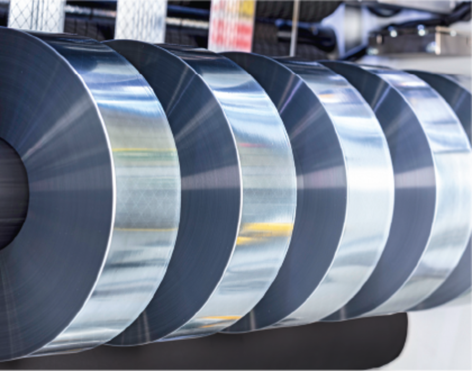
Precision slitting technology
KAMPF MicroSlitter platform features:
- Sensitive direct-drive technology with centre/surface drive.
- Fully integrated unwinder with a pre-compensation roller and tension-measuring roller.
- Precision straight and wave cutting with high shape accuracy.
- Different wavelength and amplitude options.
- Expanding shafts with expansion ranges tailored to different core dimensions.
Flexibility for your production requirements
Available platform options include:
- Pre-clearing device.
- Pinhole counter.
- Edge-trim disposal.
- Camera system for process control.
- Handling cart for finished-roll removal.
These describe supplier-platform features and options. Dhruv's installed configuration and the production route for each order are confirmed during technical review.
Wave cutting in focus
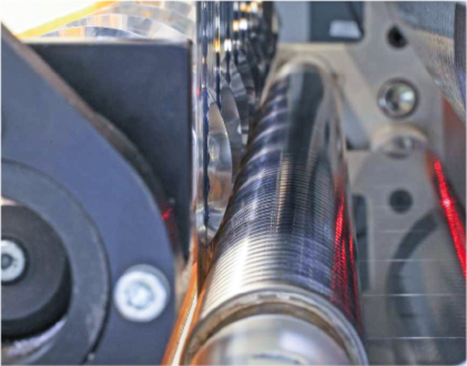
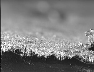
Improved end-spray contact
At the contact edge, wave cutting combined with an appropriate winding offset helps improve the connection between the metallized film and the end-sprayed metal layer. A well-formed connection supports low dissipation factor and high pulse-current capability.
Support for demanding current loads
Wave cutting can complement heavy-edge metallization. The reinforced metallized edge and selected wave geometry work together to support the end connection under demanding pulse and inrush-current conditions. The achievable current rating depends on the complete capacitor construction.
Reduced stress at the free margin
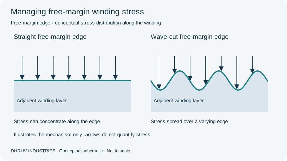
Thin polypropylene films wound under high tension can develop concentrated stress near the free margin, potentially damaging adjacent metallization. Wave cutting along this edge helps distribute mechanical stress and reduce the risk of damage, particularly at elevated operating temperatures or high currents.
Precision geometry, customised to your design
Wavelength is the distance between successive matching points on the wave. Double amplitude is the full peak-to-trough height. These dimensions are selected with film width, margin and winding offset to achieve a repeatable edge profile suited to the customer's manufacturing process.
Wave-cut benefits depend on film construction, metallization, winding conditions and the end-spraying process. Finished-capacitor performance is validated by the capacitor manufacturer.